Thursday, 22 November 2012

Lecture 6: Digital Image Processing

The Benefits of Digital Image Processing

  • Allows greater license to edit images, its scales and chemicals.
  • Allows the user scope to experiment with images, with its flexibility allowing an environment for various changes.
  • It is a significantly enhanced product in comparison to traditional darkroom photography offer more options to enhance, transform and manipulate images
Digital Camera Imaging Systems

An image capture system contains a lens and a detector, which is often a charged coupled device (CCD). This is a linear or matrix array of photosensitive electronic elements. A traditional film frame's measurements are normally 36 x 24 mm, while typically a CCD array is six times smaller, measuring 6 x 4 mm. As a result of the reduction in frame, a digital camera's lens system must be of a sufficient quality, to allow the condensation of the image to an area 36 times smaller.


Digital Camera Image Capture


On an area array sensor, thousands of microscopic photocells are placed on a grid, these  analyse small portions of the image, formed by the lense system, to create picture elements by sensity light intensity.


Sensor Spatial Resolution


"Pixelization" occurs when the resolution of the sensor array is too low, giving a blurry effect. Increasing the number of cells in the sensor array increases the resolutions of the captured image. Sensor devices today tend to have more than one million cells.


Digital Camera Colour


Filters are placed over the photocells to capture images in a combination of red, green and blue. Each area assigned eight bits numbers, giving them 256 values for colours. Typically the range is from 0-255. Each colour is a combination of red, green and blue. Red for example is 255-0-0, green is 0-255-0 and blue is 0-0-255. 


Shades of green, blue and red which aren't quite as vibrant can be achieved by reducing the value, such as changing the above red example from 255-0-0 to 128-0-0 would make the colour of red roughly half as strong.


Achieving other colours which are not red, green or blue is achieved by combining at least two of the red, green and blue options. For example. the colour purple is a combination of red and blue.


Digital Camera Optics


Before the light collected by the lens is focused on to the sensor array, it is passed through an optical low-pass filter, which serves to:


  • Exclude any picture data, beyond the sensor's resolution
  • Compensate for false coloration caused by drastic changes to colour contrast 
  • Redruced infrared and other sources of non visible light, which may disturb the imaging process carried out by the server


Moire Prevention and Removal


  • Moire is a repetitive pattern of wavy lines or circles which can appear on objects in digital captures.
  • It tends to happen when the patter of the imaging chip in the camera matches the fibers or fine parallel details in an object.
  • Some cameras incorporate anti-aliasing fitlers, which slightly blur tiny details of objects although others don't as it may compromise the level of image sharpness.
  • Regardless of whether the filters exist, digital cameras have the ability to create more.
Digital Image Fundamentals

  • Digital images are called bitmaps or raster-scan and are composed of an array (grid or matrix) of smaller units called pixels (picture elements)
  • Every pixel in the digital image is a uniform patch or colour, but when on the display screen it is a phosphor dot or stripe, consisting of a mixture of red, blue and green
The Pixel

  • The smallest digital image element manipulated by image processing software
  • They are individually coloured but as a result of their finite size, the colouring of a subject is only approximate.
Bit Map Graphics

A bit-mapped colour image is represnted in a digital memory as an ordered array of groups of bits. Each group codes colour for single pixels on the screen, meaning each pixel requires 24 bits - 8 for red, 8 for green and 8 for blue.

If the resolution of the file is 640 x 480, with each pixel being represented by 24 bits, the image size would be as follows:

640 x 480 x 24 = 7372800 bits - approximately 7.4MB

Dynamic Range

In a visual scene, the dynamic range is typically the number of colours or shades of grey represented. However, in a digitised image it is fixed as the number of bits used to represent each pixel in an image. This determines the maximum number of colours or shades of grey in the image pallette, which is formed by the specific colours used.

Bit Depths:

1 bit depth: Only has two values, black or white. A process named half tone can help simulate the colour grey by the way it spaces the black and white pixels.
8 bit depth (grey): This bit depth can represent, 256 (2 to the power of 8) shades of grey
8 bit depth (colour): Similar to the directly above, except it can represent 256 colours rather than shades of grey
24 bit depth: Known as true colour, 8 bits are used to represent each of the three additive primary colours (red, green and blue) and each pixel can represent over 16 million (2 to the power of 24). It also removes any countering which is visible at inferior bit depths.

Colour Palette:

A system palette is used when a computer system predetermines the palette and the colours, for example 256 in an 8 bit image, are used for all images. The image's appearance can be aided by selecting the 256 colours most appropriate to that image. However, this adaptive palette can cause problems, when multiple images are attempting to displayed. One palette has to be chosen and stuck to, regardless of how appropriate it is. It may be advisable to use foresight when choosing a palette.

An optimised palette is better to use than a non-optimised palette. The colours are more natural appropriate to life than in a non optimised palette. There is also less contouring, making the image appear more clear. The colours used in a non-optimised palette tend to neglect natural effects such as shading and using an optimised palette makes the image appear more altogether realistic.

The Four Categorisations of Digital Image Processing:


  1. Analysis: Operations provide information such as colour count and intensity.
  2. Manipulation: Content altering operations such as cropping and colour changing.
  3. Enhancement: Improving quality, such as better contrast or heightening images
  4. Transformation: Alter geometry, such as rotation

Processing Digital Images:

Firstly, the image is converted from analogue to digital (digitisation) and placed in a frame buffer, from here the digital image processing operations take place in the computer before it is passed back out to a frame buffer, following on from this the colours (red, green and blue)  are looked up and they are each converted back to analogue and then the image is displayed.

Histogram:

A histogram is a graph which analyses intensity levels of an image. The graph ranges from 0 to 255 in a typical 8 bit scale. An image with good contrast and dynamic range shows a full use of the intensity ranges, an image with good contrast shows some vacant intensities and a low contrast image shows a high number of vacant intensities. Histograms tend to showcase the fact that pixel intensity is either high or low, it is very rarely in the middle.

Transformation:

Digitial Image Processing allows rotation and free rotation of images. Rotation is changing the position by a 90 degree angle or a number of 90 degree angles. This is achieved by remapping pixel positions in the rows and columns. Free rotation is achieved by moving an image by an angle of your choice, which often changes the shape of the image, the interpolation works out an appropriate colour value for each pixel position in the outputted image.

Manipulation: block fill is achieved by selecting an area to change and pixel addresses are tested and modified.

Enhancement: Filtering puts a kernel to use, moving over the image in pixel by pixel steps. At each of these steps, the elements of the kernel multiply the current pixel value and are then tallied up to achieve new pixel output value. Depth can be useful to accentuate a particular part of an image as it blurs the surroundings. The smaller the depth, the more accentuated the subject becomes and the more blurry the surroundings become. Motion blur can also be added to images to give the effect than an image was taken at a time of high movement.




Tuesday, 20 November 2012

Lab 2: Exploring Cool Edit Pro

Welcome to the review of my first lab session in Audio, Image and Video Processing. This blog will be all about putting the theory explained in the other labs. Cool Edit Pro is the application we will be using to edit sound and the purpose of this lab was to get acquainted with the features of the program.

The first step was to download wav files to edit. A quick internet search took me to a website called http://www.wavsource.com which provides internet using with free wav files to download, mainly clips from films.

The task specified to identify four or five, upto 150KB in size. I did accordingly, with the largest of my five being an extract from Apocalypse Now which was 99KB in size and also to note their duration, which were as follows:

  1. Back to the Future "you can achieve anything" - 5 seconds
  2. Braveheart "they may take our lives" - 5 seconds
  3. Apocalypse Now "insane" - 30 seconds
  4. Cast Away "Wilson" - 12 seconds
  5. Shrek "Singing" - 5 seconds

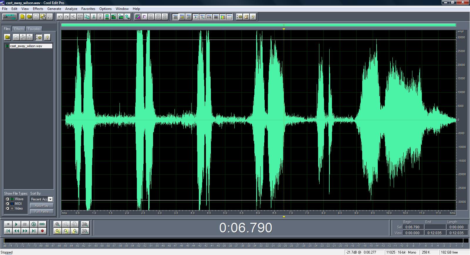
I opened up the Cast Away file and played it. In Cool Edit Pro, the sound waves appeared as follows:


By looking carefully, you can see a yellow cursor at the start of the wave. This can be moved by the user. If it is moved and you click play, then the playing will commence from the where the yellow cursor starts. The below image depicts the yellow wave starting further on.


As you can see the yellow cursor is now stationed further along the wave. Another way of noticing that the sound is set to only be partially played is the number underneath the sound. The first image is "0:00.000" whereas the second is "0:06:790" meaning that upon clicking play the sound will be played from roughly 6.8 seconds until the end.

This part of the file can be saved on its own by highlighting the area using the mouse (similar to how you would in a word processing package) and then clicking File > Save Selection. It is crucial to give it at least a slightly different file name, so your first file does not become overwritten. I simply added "_2" to the file name whilst saving, making it "cast_away_wilson_2.wav".


Here is a result of saving the section. The wave now appears in a different shape, and the total duration has been trimmed from 12 seconds to under five seconds.


The task then recommended to try the standard edit commands in cool edit pro:

  • Copy
  • Paste
  • Delete
  • Trim
  • Select Entire Wave
  • Undo


The above wave incorporates the features, cut and paste. By highlighting a wave similarly to how I mentioned before and right clicking, I clicked "cut" I then chose the area I wished the section to now play at. For simplicity reasons, I chose to add it to the end of the file, right clicking and then selecting "Paste", you can audibly hear the difference, as the end of the clip contained music which gave a "fade-out" atmosphere. The edited wave hears the music fade-out, before playing the desired section from the start. I then tested the undo function, clicking "Edit > Undo Paste" followed by "Edit > Undo Cut" which reverted the image to its original state.

I then tested the "Copy" command, taking the same section that I previously "Cut" and again placing it on the end of the file. This time, as I chose "Copy" and not "Cut" instead of the sound being moved to the end of the wave, it's repeated at the start of the wave, now playing twice, increasing the duration from twelve seconds to roughly sixteen. The wave appears as such:


I then attempted the "trim" function next. This function crops a wav file, leaving only the highlighted part and making the rest of the file disappear. This can be handy if you are looking to extract a small part of a file, a single word perhaps. This is how my attempt at trimming appears:


The final command was "select entire wave". This one was fairly self explanatory, it just highlights the entire wave. This can be done by using the edit menu, or by pressing "ctrl" and "a" which is almost universal in computer programs for meaning "select all".


The next task was to "File > Open Append" two other sounds onto one which was originally loaded. Upon doing this, the system highlights to you with red and blue toggle functions where each sound starts and finishes. This basically adds the two files that were imported through the "open append function" to the file which is already open.

By default, Cool Edit Pro measures time in seconds, but I'm going to experiment with a different time measurement. This is done by clicking "View/Display Time", which gives you a list of options. I chose to change from "decimal" (seconds) to "samples" 


The waveform itself does not change, but the units of measurement do. In samples, they range from 0 to roughly 55000, where as in decimal the range is from 0 to roughly 50. 

Next I explored the different options available in the vertical axis. Below are screenshots of each of the settings for the vertical axis, which depicts the volume of the sound at each point of the wave. The difference in values is visible on the right hand column next to the wave.

1. Sample Values (Default)


2. Normalised Values (Ranging from -1 to 1)


3. Percentage (0% being the minimum, 100% being the maximum)


4. Decibels (dB standard measurement)


For the next part of the exercise, I opted to open another wav file. This part of the exercise required select parts and zooming in and out. The wave appeared as follows without any alterations


Zooming in on a certain section, by using the buttons underneath the wave leaves it looking like this:


This zooms in on the first word in the clip. Words are recognisable in Cool Edit Pro as the parts with high amplitude. Parts with prolonged sections of low amplitude are gaps in speech. Although I was able to determine where the first word would start and finish. I double checked by playing the sound back.

If you zoom in far enough you can see each individual sample as shown below.  After exploring this, I zoomed out to give the image its original state.


I then went on to try some effects with the sound, which were as follows:

Invert- brings the amplitude closer together and cut's down on harsh sound between words.


Reverse- plays the sound backwards.


Silence- removes the amplitude of the sound, meaning it appears as silence.


Modifying the amplitude of an image is also a feature of Cool Edit Pro. In its original state, the peak amplitude of the waveform is 100%, by clicking Effects > Amplitude > Constant Amplitude and choosing the 6dB cut option, it decreases the amplitude, making the peak 50%. Both the images are shown below, the original followed by edited one. Having played the second one back, the sound is not quite as loud. Afterwards I boosted the amplification by 3db, which showed a peak of approximately 70% and then added 3dB once again to bring it back to it's original state. The third image is also shown below. The user can normalise the amplitude by clicking Effects/Amplitude/Normalise and you can select a percentage to normalise to.


Fade In/Out

Two other effects of Cool Edit Pro are too "Fade In" the amplitude and to "Fade Out". The former means the sound is edited in a way in which it starts off quietly and increases towards the end. "Fade Out" is the opposite, it's starts loudy but quietens down as the sound progresses. Both are shown below, "Fade In" first, followed by "Fade Out". Notice that in the first one, the higher maximum amplitude is towards the end of the wave, whereas in the second it is fairly close to the beginning.


Thursday, 15 November 2012

Lab 5: Digital Signal Processing- Editing Sound

Digital Signal Processing

This week's blog is on the subject of digital signal processing. To start with I had to download a file "speechtone.wav" to edit in CoolEditPro (the software used to edit sound). When I opened CoolEditPro and loaded in the downloaded sound, the wave initially had this appearance:


I then listened to the sound for the first time. There was a highly annoying background tone, which had a sort of piercing sound. The speech in it was far from precise and the overall sound resembled a radio frequency which was going out of range. I thought one way to change this would be to edit the notch filter, adding in tones of 440HZ. Below are the standard frequencies applied to sounds in the software. 


Firstly, I experimented with only applying a 440Hz sound to see how that would affect the sound, to see if it could make the sound more clearer and try and remove the piercing tone if possible. Below denotes how I edited the settings of the notch filter.


The wave then changed in appearance to look like this:


This method added far more clarity to the speech contained in the sound file, but the piercing tone remained, so I then opted to try something different to improve the quality of sound. Instead of solely using a Notch Filter at 440Hz, I thought trying to add a notch filter at that frequency to the standard settings would be beneficial. I edited the notch filter as follows:


This then made the wave take this shape:


By this point, the speech is getting far clearer and the muffled tones that resembled at out of range radio have all but disappeared, but the piercing tone on top of the speech still remains, so my next move was to try and remove that. Having analysed both of the methods, I came to the conclusion that the first one was better, so I edited the notch filter settings accordingly. 


Thursday, 8 November 2012

Lecture 5: Light

Looking at Light

The light generated, transmitted and reflected by the objects in our surroundings allows the human eye to view, record and interpret the world around us as images.

It is worthwhile distinguishing between the following concepts

  • Looking - arranging what you can see
  • Seeing- receiving light energy and converting it into nerve impulses
  • Observing- the analysis, interpretation and classification of nerve impulses in terms of objects or effects

The Sun:

The sun has the most prominent impact on natural lighting, powerful enough to completely alter the appearance of any image. The sun rising and setting sees a change of light very visibly, including a immense shift in colour.

Both when rising in the morning and setting in the evening, the sun produces long shadows, whereas in between times, peaking in the middle of the day, it produces short shadows.

In the middle of the day, the sun can be referred to as "white" light as it represents the most even mixture of all colours from the spectrum. This could be described as "colourless" and in the middle of the day. 

Below is an example of the Empire State building, New York showcasing how the varying sunlight at different points in the day can alter the feel and colour of an image.


The colour of an image can be altered significantly depending on the time of day. The main points in the day when the sun greatly affects the colour of the image are, predawn, morning, mid day and twilight. Below are images of The Eiffel Tower, Paris in that order, showcasing the differences.


The predawn photo shows a dark blue sky with red tinges, as the sun is yet to rise. The Eiffel Tower itself is very dark at this point in the day, outputting little or no brightness at this time of the day.


The morning image is transformed completely with the brightness of the morning sun altering many effects. The red tinges in the sky have become brighter, more yellow, in the process. The sun shining on the tower itself outputs a far more vibrant colour, with increased light and brightness. In turn, the increase in light makes the formation and the features of the tower far more visible.


The midday image shows the image in its most natural light. This is down to, as previously mentioned the insertion of "white" light, the most even represenation of the colour spectrum. Although it shows The Eiffel Tower in its most natural state, the reduction in light shining down on the tower in comparison to dawn means, the detail in the architecture is slightly less.


The twilight image shows a darker, dim display of The Eiffel Tower. In parts you can see the reduced detail in the architecture, but for the most part it is artificially lit up, which limits the analysis of natural light effects. As the sun is setting, the red hinges, visible in the predawn image, are beginning to return. The blue colour from the daylight is beginning to darken without the influence of the sun.

Clouds in the sky soften and diffuse light, spreading it more evenly, although the light coming from the sun on a cloudy day may appear white to the human eye. The diffusion of light is a very useful method and can often be used as it helps correctly emphasise the intended object of the picture. An example of where the diffusion of light is commonly used would be a portrait. 

Below is an example of light diffusion in a potrait:


The play of light in images is down to three factors:


  • Direction
  • Contrast
  • Colour

Direction:

The direction that the light is striking an image is vital, there are three types of image illumination which are:

  • Front-lighting
  • Side-lighting
  • Back-lighting
If you are observing an image and a source from behind you shines directly onto the object, this is termed as front lighting. Side lighting is the creation of strong shadows to emphasise texture, making the image more defined, in elements such as shape dimension and depth. As the name suggests, back-lighting is the opposite of front-lighting, with a source behind the object of image creating lights and other effects.


Contrast:

An image which has the attributes of being high-contrast would be likely to be one taken in increased sunlight. The intensity of the sunlight is responsible for producing sharp and highly visible details and effects such as saturated colours.

Low-contrast images are the opposite. They are more likely to appear in overcast situations as I previously touched on the fact that clouds diffuse (or scatter) light, making the colour in images appear more balanced, evenly distributed and less bright. This is due the gradual blending of tones, this reduces the shocking vibe that may be more present in high-contrast images.

High contrast images can be useful in times where a particular emphasis is required on an object which has been subjected to the light. Low contrast images are more useful in situations where you are looking to capture detail in an image, where it may not be as visible in high contrast situations.

Colour:

Colour film has a higher sensitivity than the eye and can produce unwanted tints to images taken in a certain light, such as green on fluorescent lighting and orange on daylight. Image processing can help overcome this and modifications by the user can achieve the view of the picture they had hoped for.

The human eye is attracted to colours, particularly bright colours. Colours used in images can often depict the mood of a picture and the author may use this to his advantage. Instinctively, humans attribute certain colours to certain feelings and attributes and using colours effectively may help an image be appreciated by its intended audience in the correct way.

Standard characteristics of colours:

Yellow:

  • Bright
  • Cheerful


Red
  • Exciting
  • Warm
Green and Brown
  • Calm
  • Restful
  • Natural
Blue
  • Very much varying on shade, can be contrasting or subdued.
Modifying light in images can give you a better foothold on how you intend to express an image. Modifications of colour, contrast and brightness can give an image an effect that was intended or possible in its original state. 


Tuesday, 6 November 2012

Lecture 3: Hearing

Hearing

The human auditory system can detect quick alterations in decibels (also referred to as loudness or sound intensity) and frequency (also referred to as pitch). The responsibility of the auditory system is to convert air pressure changes in to activity which the human brain can recognise and assign a meaning to.

Each part of the ear has different responsibilities and performs different sound functions.

External Ear: Capture, Focus, Filter

Middle Ear: Concentrates Energies

Inner Ear: Tranduces sound into neural activity

The process of hearing:

Sound waves are gathered by the outer ear. The outer ear consists of the external ear, alternatively known as the pinna and a canal leading to the eardrum. The external ear's configurations amplifies the sound, particularly in the frequency range of 2000-5000Hz. This range is typically when speech can be recognised. The shape of the external ear can be important for local sound.

Sound waves vibrate the ear drum from the canal, vibrating three bones in the middle ear, known as the malleus, the incus and the stapes. The vibration of the stapes transmits amplified vibrational energy to the fluids of the cochlea, by vibrating a small membrane at its base. A round window separates the middle ear and the canal.

The complexity of the structures of the inner ear are vital to the process of turning sound into neural activity, i.e. making it recognisable. The cochlea is the term used for the auditory section of the inner ear. The top is referred to as the apex, where as the bottom (closest to round window) is the base of the spiral.

There are three parallel canals situated along the length of the cochlea:

  • Tympanic Canal
  • Middle Canal
  • Vestibular Canal
Situated between the middle canal and the tympanic canal is the basiliar membrane a flexible structure containing the necessary elements for converting sound into neural activity. The basiliar membrane is five times as wide at opposite ends of the cochlea. Its at its widest at the apex, narrowing towards the base. It is responsive towards vibrations initiated by sound transmissions to the fluid-filled cochlea deflected by the oval window, started by the bones of the middle ear.

High frequency sounds displace the narrow base of the inner ear, mid frequency sounds traditionally displace the middle of the basiliar membrane and the low frequency sounds tend to displace the apex.

The organ of Corti is the term for used collectively for all the elements central to the transduction of sounds, it has three main structures - the sensory (hair) cells , an elaborate framework of supporting cells and the terminations of the auditory nerve fibres. At the top of the organ of the corti is the tectorial membrane. The outer hair cells extend to indent the base of the tectorial membrane.

Fluid movements in the cochlea produce vibrations of the basiliar membrane. The inserted steroscilia bend, the direction of the bend determines whether the hair cells increase or decrease the rate the auditory nerve fibres fire at.

Wednesday, 31 October 2012

Lecture 2: Digital Sound Processing

Digital Sound Processing

Digital Sound Processing System in Stages:
  • Signal In
  • Band Limiting
  • Analogue to Digital Conversion
  • Digital Signal Processing Operations
  • Digital to Analogue Conversion
  • Smoothing
  • Signal Out
Signal Processing is an area of electrical and systems engineering along with an applied mathematics formula which analyses and performs operations on signals in either discrete or continuous time periods in order to produce useful operations from these signals.

Signals are analog or digital and electrically represent a variation in time or space in physical quantities.

Electronic Filters

Electronic filters are electronic circuits which perform functions of signal processing. There can be two reasons for this
  • Remove frequency components from the signal
  • Enhance existing frequency component
Electronic filters can be:

  • Passive (a component that consumes but does not produce energy or a component incapable of gaining power) or Active (a type of analogue electrical filter, recognised by the use of one plus activite components, such as different types of amplifiers, such as voltage or buffer
  • Analogue or digital
  • High Pass Filter- a device that passes high frequencies and reduces the amplitude of frequencies which are measured at more than its maximum cut off point
  • Low pass filter- passes low frequency signals but reduces the amplitude of signals with above maximum frequencies, it is the opposite of a high pass filter and is also known as a high-cut filter or a treble cut filter when used in audio applications
  • A band pass filter- a combination of high and low pass filters.
  • A band stop filter/band rejection filter- passes most frequencies in their original state but alters some within a specific range
  • Discrete time or continous time
  • Linear or non Linear
  • Infinite Impulse Response- deals with filters with an impulse response over an infinite length of time or Finite Impulse Response which give fixed time responses
Pitch

Pitch is a perceptual concept with allows the human ear to oder sounds on a frequency related scale. High and low pitches are compared in relation to musical melodies, which require sound with a claer frequency is clear and stable enough to be heard as something more substansial than just plain noise. Pitch is considerd a major auditory attribute of musical tones, along with duration, loudness and timbre.

Digital Signal Processing System Requirements:

  • Input and output filetring
  • Conversion from analogue to digital and vice versa
  • Digital processing unit
Why choose Digital Signal Processing?

1. Precision

Although theoretically digital signal processing is limited only by the process converting input and output (analogue to digital and digital to analogue) in practice word length (number of bits) and sampling rate (sampling frequency) aid modifications. The ever increasing operating speed and modern word length is increasing the areas of application.

2. Robustness

Logic level noise margins benefit digital systems, making them less susceptible to electrical noise and component tolerance variations, in comparison to analogue systems. Vitally, adjustments in complex systems for electrical drift and component ageing are virtually removed in complex systems.

Electrical noise is a random fluctuation in an electrical signal. There is a large scope for noise generated by electronic devices as there are various different effects which can lead to it being produced.

Component tolerance variations may be specified as a number of things:


  • Factor/Percentage from the nominal value
  • Maxiumum deviation from the nominal value
  • Explicit range of allowed values
  • Implied by the numeric accuracy of the nominal value
Electrical drift is when an undesired progressive frequency change occurs. Main causes for this are the ageing of the components and changes in the environment. It can happen in either direction, the frequency can increase or decrease.


3. Flexibility

The programmability of digital signal processing caters to aid processing operations by expansion and upgrading, without majorly significant hardware changes. It is possible for a user to constuct a practical system with suitable characteristics such as time varying in order to allow adaptations.


Sound Card Architecture


  • Spatial anti-aliasing is the technique that helps minimise aliasing when representing a high-resolution image at a lower resolution than its original state. This means that if you are attempting to reduce a pictures file size and display it, the detrimenta, l effects of the picture will be as limited as possible. It is used in many applications, including digital photography and computer graphics. Anti-aliasing is often used prior to converting from analogue to digital in order to remove the out of band component of the signal
Sampled Data Reconstruction Filters

  • The input of Analogue to Digital Conversion requires a low-pass analogue electronic filter named the "anti-aliasing filter" as described by the sampling theorem.
  • The sampled input signal must be bandlimited to prevent aliasing, which means waves of a higher frequency being recorded at a lower frequency
  • Likewise, a low-pass filter is required in Digital to Analogue Conversion to prevent aliasing, in this occurrence waves of a lower frequency being recorded at a higher frequency
Implementation

  • Sine waveforms have infinite signal responses, both negatively and positively a practical filter is require as it has a non flat frequency
  • Some systems have an anti-aliasing filter and a reconstruction filter. They are often identically designed due to input and output both being sampled at the same frequency, 44.1KHz.
  • Both attempt to block sounds above 22KHz and as far as possible pass sounds below 20KHZ.
  • Theoretically, Digital to Analogue conversion is a series of impulses but is better described as a series of stair steps.
  • The low pass reconstruction filter evens out the gap between the metaphorical stairs, remove the harmonics below the required limit
Sound Cards

  • A poorer quality of sound card can result limitations in sampling rates, this can be particularly clear in devices such as Notebook PCs
  • Most modern sound cards have a 16 bit length, meaning they can represent 2x16 values (65536) different signal levels within the input voltage range
  • Quantisation step size can be worked out by dividing the word length by the range.
  • Q = 10/65536 = 0.15MV
  • The above is a calculation for the range of 10V